By Dr Alan Marson
As technological advancement and experience increase within the offshore wind industry, it has become both possible and economically viable to push monopiles into deeper and deeper water and use larger and larger turbines.
Here at Empire Engineering we discussed this very topic at length in our Tech Session webinar entitled: ‘How deep can the Monopile go?’
However, an inevitable consequence of this is that we require bigger and bigger diameter monopiles.
What does this mean for the designer?
One outcome of this is having to increase steel thickness to meet the Diameter (D) to Thickness (t) ratio criteria as set by many codes when analysing tubulars. Typically, standards limit this value to less than or equal 120 (DNV, ISO, Norsok) meaning that for, say, a 10m diameter monopile the minimum thickness, regardless of analytical results, is 83mm. When we further increase, for example to 12m diameters, the minimum thickness then becomes 100mm.
This requirement is regardless of any stress calculations or other analytical results. As a consequence, D/t requirements may dictate that large diameter monopiles became disproportionately, and perhaps unnecessarily, heavy. Wasting both steel, and ultimately, money.
But where do these limits come from?
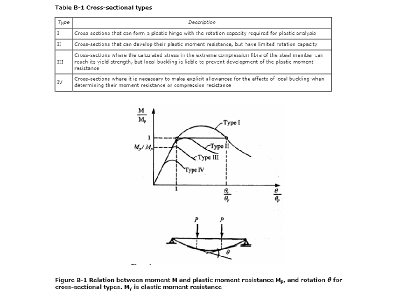
Well, primarily it’s related to the buckling behaviour of tubulars. The reader might recall that column sections can be classified as one of four types depending on their slenderness. The distinction between these types is based on the relative yield strength to buckling behaviour, figure from DNVGL 0126 below, and dictates whether local yield, column buckling or local buckling is likely to be the compressive failure mechanism. Theoretically, any Type IV section should require a local buckling assessment.

Talk with a specialist
We've been a part of some of the worlds most exciting and
complicated projects in offshore wind.
If you need more eyes, brains and hands, we're ready to help.
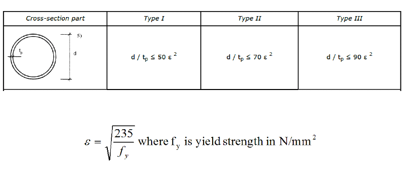
The assessment of type depends on the yield strength of the material. See the example of type for tubular, DNVGL below, where anything that doesn’t fit into Type III is automatically Type IV.

By this reckoning, any tubular made of S355 with a D/t ratio larger than 60 falls into the most onerous category: Type IV! This is why shell buckling checks are already required for monopiles.
Should we be concerned?
I am probably getting ahead of myself here, because before we can worry about a pile buckling in-service, we’ve got to fabricate, then transport, and then install it. Fabrication and transportation produce their own issues; supporting such slender piles without overstressing the cans at the support points or ovalising too severely represent quite severe challenges. Having said this, one study has suggested that D/T ratios of 160 are feasible under these limitations, although I am sure some installation contractors would beg to disagree.
So, let’s assume from that we can push it to 160. We then quickly hit up against the rules in DNVGL-ST-0126. The code doesn’t prescribe how this should be treated, but instead Section 4.5.1.2 (July 2018) allows checking of tubular members using four possible codes:
- DNVGL-RP-C202
- EN1993-1-1 & 6
- ISO 19902
- Norsok N-004
The latter two are explicitly only for D/t ratios less than 120 and refer back to DNVGL-RP-C202 for D/T greater than 120. Similarly, EN1993-1-1 is also limited to D/T of 120.
This leaves us with DNVGL-RP-C202 (ignoring EN1993-1-6 which is a similar shell buckling approach anyway). And this is where things get both interesting and complex (which to me is the same thing, of course).
Thankfully, this code provides us with a method of extending beyond ratios of 120 by analytical (mathematical) methods, at least in theory. Here, the capacity depends on the square of the thickness, and indirectly on the radius (and therefore diameter) in the reduced buckling coefficient.

How about justification using FEA?
Well, on the surface this appears tempting, until we come across the complexity of imperfections. Ultimately, buckling is driven by the imperfections, and a geometrically perfect FEA model will be non-conservative when it comes to calculating failures. Careful attention will have to be paid to the fabrication class and tolerances that can be achieved by the fabricator.
Better and better tolerances will be required to have confidence in the stability of the monopile. In addition to this, the relative reduction in wall thickness will mean the effects of slightly misaligned axial loads will become more and more important, especially combined with potential imperfections.
Ultimately, we are pushing the boundaries between the geometrically perfect analytical results and the practical realities of the real world. Getting the correct balance is not easy and requires a good understanding of all the factors involved – accurately including the potential misalignments and manufacturing tolerances to create the most representative result. Inexperienced practioners can very easily produce non-conservative and unsafe results if the full array of buckling considerations aren’t properly considered.
In conclusion, the technological advancement and increasing experience that is leading to the possibility of larger turbines in deeper water will have to be matched by similar progress in the design process. The further we push methods developed for smaller diameters the less representative of the real world they become. The challenge of better understanding and optimising D/t ratios for larger diameter monopiles is one that comes with great rewards; saving material, weight, money and headaches – something we all need less of!
To find out more, please get in touch with the team at Empire Engineering.


