By Aaron Du
Empire’s recent webinar An introduction to floating offshore wind has led to lots of discussions about floating wind foundation concepts. Within that discussion, one of the questions that keeps on coming up is,
“how to select floating wind foundation concept types?”.
To determine which floating wind foundation type is suitable for your project, qualitative and quantitative approaches can be applied. This article provides a high-level guidance of how to evaluate different floating wind foundation types:
- A qualitative comparison between semi-submersible, spar, and TLP, the three most popular types of floating wind foundations, is presented from various perspectives, including design, fabrication and transportation and installation (T&I);
- A quantitative approach – concept level design and analysis is also discussed from three aspects: design challenges, methodology and scope.
Comparison between semi-submersible, spar and TLP
Common Features of Floating Wind Foundations
Floating wind foundations need to have adequate buoyancy and stability to support the wind turbine rotor nacelle assembly (RNA) and tower. They are typically hull structures fabricated of stiffened steel cylindrical shells or concrete.
A floating wind foundation has a complex behaviour responding dynamically to wind, wave and current, involving six rigid-body modes of motions: heave, sway, surge, pitch, roll and yaw. The motions of the floater are coupled with the aerodynamics from WTG and hydrodynamic mooring system. The inertial loads due to accelerations of the body in motion is important. The aerodynamic effect on the floating wind turbine is significant, even in a small motion, since the centre of gravity of the turbine is very high. The coupling effect of motions between the foundation, WTG, and mooring systems becomes increasingly more important as water depth increases.
Talk with a specialist
We’ve been a part of some of the worlds most exciting and
complicated projects in offshore wind.
If you need more eyes, brains and hands, we’re ready to help.
Semi-submersibles
Semi-submersibles typically consist of multiple columns and pontoons. The columns mainly provide the stability, while pontoons provide additional buoyancy. The centre of gravity is above the centre of buoyancy, the stability is achieved by the restoring moment of the columns. The floating structure is kept in position by a mooring system, consisting of catenary or taut spread mooring lines and drag or suction anchors.
To optimise the foundation structure and achieve wind turbine stability, various innovative floating wind semi-submersibles have been created by different floating wind prototype designers. For example, WindFloat (Figure 1) developed by Principle Power has three large diameter columns with small diameter braces made of steel; The VolturnUS (Figure 2) design utilises a concrete semi-submersible floating hull.
The wind turbine can be positioned at the centre of the floating unit or on top of one column. In the latter case, additional ballast is needed to counteract the weight of the turbine.
Although semi-submersibles have poorer fundamental stability than Spars and TLPs, this concept is still the most popular concept so far in the industry for the following reasons:
- It can be applied to a wide range of water depth typically from 40 meters water depth.
- The cost of anchoring system is lower than TLP.
- Its transportation and installation is simpler than the other two concepts.
- The turbine can be installed on the semi-submersible in the dockside and towed out to the site, avoiding the costly offshore installation.
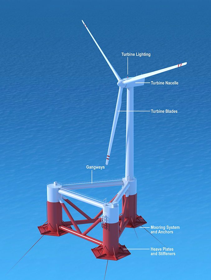
Figure 1, WindFloat, Principle Power
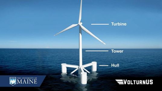
Figure 2, VolturnUS
Spar
A Spar foundation is a large diameter vertical buoyant cylinder ballasted (at the bottom end) with a deep draft, which makes the structure less responsive to wind, wave and current. Similar to semi-submersibles, the spar foundation is kept in position by catenary or taut spread mooring lines with drag or suction anchors. The world’s first floating wind farm Hywind uses spar foundations (Figure 3).
The Spar concept has the following advantages:
- It is more stable than semi-submersible because of its deep draft design
- Spar’s structure configuration is normally simpler than semi-submersible and TLP
- The cost of anchoring system is lower than TLP.
However, because of spar’s tall hull structure, it can only be applied to water depth greater than 100 meters; it is challenging to remain upright during transportation in the shallow water zone; and spar’s turbine installation would most likely happen offshore, as with bottom–fixed foundations.
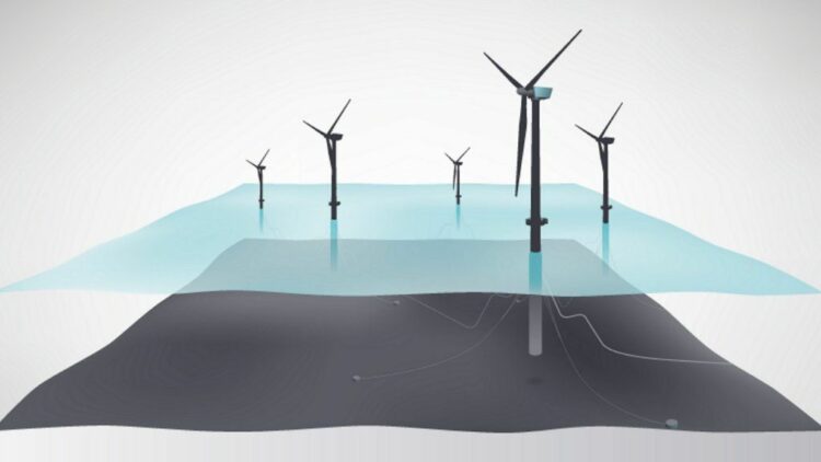
Figure 3, Hywind Spar Floating Wind, Equinor
TLP
Like a semi-submersible, a Tension Leg Platform (TLP) normally consists of columns and pontoons. The unique feature of TLP is its mooring system – vertical tensioned tendons, which provide stability to the structure. The TLP structure is vertically restrained precluding motions vertically (heave) and rotationally (pitch and roll), but it is compliant in the horizontal motions (surge and sway).
A number of TLP concepts have been developed in the industry, SBM’s first generation offshore wind floater is an example, see Figure 4.
TLP is the most stable floating concept among the three types. A TLP’s structure size can be much smaller than a semi-submersible given its stability advantage, leading to lower material cost. Similar to semi-submersible, TLP can be installed in a wide range of water depth from 40 meters, and the wind turbine can be installed on the TLP in the dockside and towed out to the site.
However, the Technology Readiness Level (TRL) of floating wind TLP is the lower than the other two concepts today. Because of the high stiffness of the structure, TLPs are normally susceptible to high-frequency dynamic loads which may produce resonant pitch and heave motions leading to fatigue damage to the tendons. TLPs also have the most expensive anchoring system among the three concepts in terms of fabrication and installation.
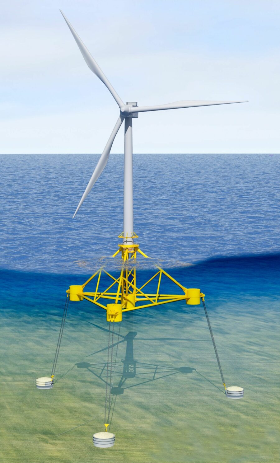
Figure 4, SBM TLP floating wind, SBM
A high level comparison between three floating wind foundation types is summarised below.
| Floater Types | Structure configuration | Stability | Water Depth | Station Keeping | T&I | Turbine installation |
| Semi-Submersible | Complex structure configuration, large size structure | Less stable | > ~40m | Simple mooring system and Low cost | Tug-towing transport and low cost | Turbine installed in dockside |
| Spar | Simpler structure configuration, tall and large size hull | Good stability | >~100m | Simple mooring system and Low cost | More challenge because of tall hull, HLV may be required, high cost | Turbine installed offshore |
| TLP | Small size structure | Good stability, but susceptible to high-frequency dynamic loads | >~40m | Complex tendon system with high cost | Tug-towing transport and low cost | Turbine installed in dockside |
Concept Design and Analysis of floating wind foundations
Design Challenges
We estimate that there have been over 40 floating wind prototype foundations developed in the industry globally. Different floater types have different design challenges. The key challenges for the whole life cycle of each type shall be identified at the concept design level. For example, sufficient floating stability needs to be achieved in both operational and temporary phases, according to DNVGL-ST-0119. Unlike semi-submersibles, stability is not critical issues for a TLP under operational conditions, because vertical and rotational motions of a TLP is far less than that of a semi-submersible, but the vertical and rotational motions are important issues to be addressed for transport and installation of a TLP. Another challenge for TLP design is to keep its natural periods below the range of significant wave and turbine dynamic loads.
Design Methodology
Although several organisations published floating wind guidance, the DNV’s standard “DNVGL-ST-0119 Floating wind turbine structures” is the typically applicable industry standard for the concept level design and analysis of the floating wind foundation and mooring system.
The concept design of a floating wind foundation should demonstrate that the designed capacity exceeds the worst possible load combinations for primary structural components. To ensure the structural safety and integrity, three most prominent failure modes shall be considered:
- Stability failure: loss of global structural stability, or global and local buckling of primary steel
- Strength failure: excessive yielding or brittle fracture of structural components
- Fatigue failure: fatigue damage under wind and motion cyclic loads
For both floating structure and mooring lines, the concept design could be primarily based on the survival condition, i.e. ULS considering 50-year extremes. Fatigue loads may also drive the design of the foundation and moorings. Although, fatigue is normally considered at the FEED level, it would be beneficial to have some understanding of fatigue by performing a preliminary fatigue analysis if feasible.
A frequency domain analysis may be used for determining the basic geometry, but time domain analysis is recommended allowing for coupling load effects.
General Scope
When sizing a floating wind foundation, the following most fundamental functions of the type need to be examined:
- Stably support the turbine under the most critical DLCs
- Minimally respond to wind, wave, and current
- An effective structural configuration
The general scope of concept level design and analysis of a floating wind foundations shall include:
- Preliminary sizing
- Stability analysis
- Hydrodynamics analysis
- Coupled motions and loads analysis including preliminary set of design load cases (DLCs) for the concept level
- Preliminary mooring (for semi-submersibles and spars) or tendon (for TLP) and anchor design
- Preliminary global strength analysis
- Preliminary drawings
- Methodology for loadout, transport, and installation
Empire specialists can effectively and efficiently assist in the selection process of floating wind foundation concept types by utilising both qualitative and quantitative approaches. To find out more, please get in touch with the team at Empire Engineering.

