By Dr Alan Marson.
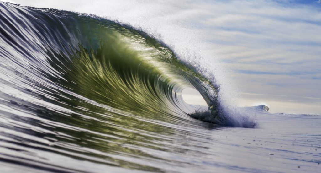
I’m not really a beach person, but beach trips have become an essential part of my kids’ Summer holidays; although being Scottish, I think it’s the novelty of warm water they enjoy the most. When I’m there, I do love watching the waves break on the shore – I find the sight and sounds of waves gently lapping on the sand very relaxing. But, when I’m analysing the impact of breaking waves on an offshore wind turbine structure, in the middle of a wild sea, it’s anything but relaxing!
Breaking waves represent a significant challenge to the design of any offshore structure.
The forces are large, and the wave theories begin to break down, or at least become significantly more empirical and uncertain. The unknowns and complexities ramp up nearly as quickly as the wave itself.
Starting with the more sedate conditions, in their simplest form, we can consider water waves as perfectly shaped sine waves, these are known as Airy waves. The water particles move in circles of ever decreasing size down to the seabed as shown in the diagram below. Everything is very neat, comparatively well understood but not very representative of the real world…
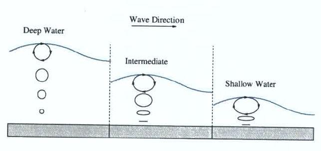
However, as water depth gets shallower relative to wave height, non-linear effects become more important, and the wave no longer has a sinusoidal shape.
The front becomes steeper and the shape less symmetric until in some cases the front face almost vertical as shown in the following diagram.

These are accounted for by non-linear wave theories such as stream theory that modify the shape, water velocities and accelerations. The non-linearity of a wave can be determined by the relative sizes of the wave height and water depth. As a wave moves from deeper to shallower water, the ratio of height to depth will change and this creates a more non-linear wave outline until eventually the wave breaks. The breaking limit in this region is when the ratio of height to depth approaches 0.78. Equally, in deep water, a wave can break simply by becoming too large, although in these conditions the limit is independent of water depth and occurs when the height to length ratio is 0.14. The diagram below shows how the complexity of the equation required to predict the wave parameters increases the closer to breaking the wave becomes.
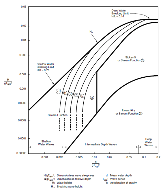
[Reproduced from API RP 2A-WSD]
Determining the shape of the wave is only half the battle of course, the load it imparts on the structure is the important part. For most (non-breaking) waves, the loading is relatively well understood using Morison’s equation. This is a semi-empirical equation derived in the 1950s where the force on a member is determined based on several structural and hydrodynamic factors, such as the shape and diameter of the member and velocity and acceleration of the water particles. There are two components to the force, the inertia component that depends on the acceleration of the water particles and the drag component, that depends on the square of their velocity. For Airy waves determining the velocities and accelerations is a simple equation; as the face of the wave becomes steeper and the shape more complex, the non-linear theories are used to determine these parameters.
The complexity of this is bad enough, and that’s even before you have breaking waves. Many companies will continue to use Morison’s equation outside the appropriate parameters – for example when the member sizes have become too large or the wave is potentially breaking. Breaking raises the stakes and complexity to understanding exactly what is going on.
Breaking occurs when the water particle velocity at the tip of the crest exceeds the wave celerity (the speed the wave itself appears to be moving at). The water itself is moving faster than the wave it’s part of, so it gets ahead of the wave and breaks. The relatively smooth flow prior to breaking becomes turbulent.
Breaking waves come in four flavours: Spilling, Collapsing, Surging and Plunging, but as collapsing and surging only occur on beaches, spilling and plunging breakers are of most interest to offshore designers. Spilling breakers occur when the tip of the wave crest becomes unstable and runs down the leading edge of the wave, creating foam. The wave crest may travel a number of wavelengths during this process and the energy is dissipated gradually. Plunging breakers are larger and more violent, the wave crest turns over, trapping air between it and the front face of the wave. These are the sorts of waves we have in mind when we think of breakers – the sort surfers yearn for and appear in any disaster movie worth its salt (… even though real tsunamis never look like that!)
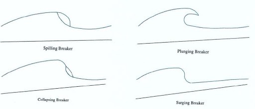

The energy of a plunging breaker is released over a single wavelength and the effects are more akin to wave slam forces than more traditional Morison’s equation derived loading; we all know how dramatic a plunging breaking can look. Morison’s equation is designed to predict the loading in an oscillatory flow, and breaking is a one-off large energy event which produces a short duration high energy impact. Therefore, directly using Morison’s equations for these predictions is never going to be entirely correct.
One approach is to consider the breaking wave as a slam load, treating it as an impact problem.
This is discussed in codes such as DNV-RP-C205 where the shock pressures from a breaking wave are to be considered, assuming the impact velocity is 20% higher than the speed of the wave itself but also a height 40% larger than the most probably largest significant wave for the return period being considered. As the loading is dependent on the square of the velocity, this represents a significant increase in the overall forces produced. But this is essentially just a modification of the wave slamming calculations based on empirical results.
Computational fluid dynamics is another possible solution. However, turbulent modelling is complex and by its very nature random. When CFD is done, is it often compared to in-situ tank-testing, which is of course the brute force solution! Coming from an experimental background, I am quite a big fan of tank testing, but it can be hard to draw general conclusions and results from it.
Another approach is to consider the problem probabilistically.
All structural analysis is fundamentally probabilistic – we make assumptions about the strength of materials and uncertainty in the load to give an acceptable probability of failure; codes are often based on an annual probability of failure of 1 in 10000. A large non-breaking wave will travel across your site, but only break over approximately one wave-length, expending most of its energy in turbulence. Factoring in the probability of the largest wave breaking directly on your structure, either theoretically or using some Bayesian statistics, could account for a large proportion of your 1 in 10000! Designing for large pre-breaking waves can be arduous enough but whilst breaking wave impacts do happen, and cause damage to secondary and even primary steel, designing your structure to withstand events that we are, at best, still estimating the power of might be a false economy. It could be suggested that for an unmanned structure, the costs and design required to prepare for and mitigate such an unlikely event outweigh the benefits of doing so.
Research on the loading of breaking wave loading is still very much on-going. The transition to turbulence, which by its very nature is unpredictable, makes calculation difficult to assess. The problem is similar to that experienced when trying to determine wave in deck loads and no doubt will continue to fascinate and evolve for many years to come, probably long after my kids have grown up and stopped asking me why I’m staring so intently at the waves…
Empire Engineering are offshore wind foundations specialists. If breaking waves are a potential concern on your site, please get in touch.
#OffshoreWind #BreakingWaves #RiskMitigation #OffshoreWindFoundations #EmpireEngineering
Talk with a specialist
We've been a part of some of the worlds most exciting and
complicated projects in offshore wind.
If you need more eyes, brains and hands, we're ready to help.

